.png)

Description
1 product Brief Introduction
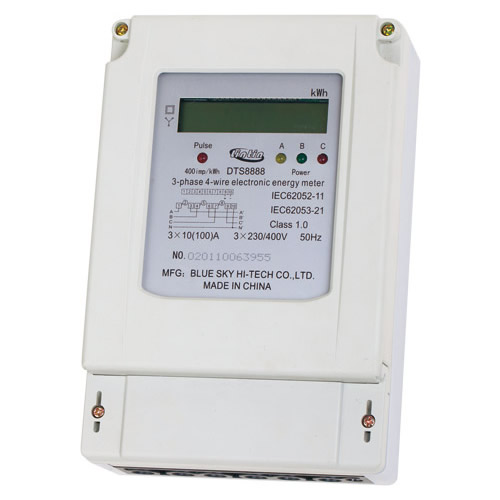
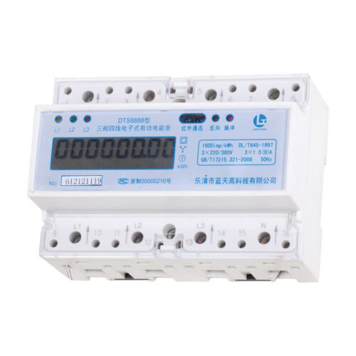
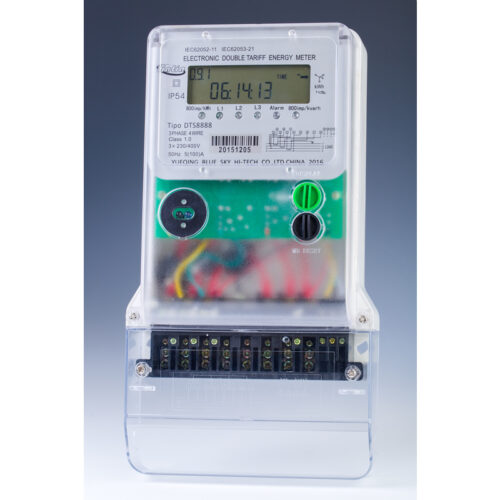
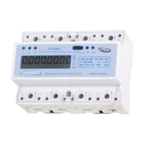
The three-phase electronic meters for active energy is the use of advanced microelectronic technology and SMT production process of products manufactured for rated frequency 50Hz three-phase AC active energy metering. Infrared and RS-485 port communication function, LCD display, set, and Chaoshou power available handheld meter reading. Has high measuring accuracy, high sensitivity and reliable performance, wide load, low power consumption, small size, light weight, easy to operate, easy to install and features, is the ideal measuring instrument of residential electricity consumption billing.
The product complies with the technical requirements of IEC62053-21 IEC62052-11 standard three-phase electronic energy meter.
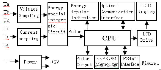
2 Principle of work and structure diagram
Users of electricity, the current sampling of the current signal acquisition circuit and voltage sampling circuit to sample the voltage signal to the power of application specific integrated circuit, In application specific integrated circuit, the voltage signal and current signal together to the multiplier circuit, a multiplier circuit output voltage and current proportional to the product of the signal, this signal after voltage frequency converter and the actual use of generated electricity into the size of proportion of energy pulse, and then pulse into the CPU processing, and thus complete Data display, infrared communications, data storage and other functions, and its block diagram are shown in Figure 1.
3 Functions and features
3.1 Measurement function
With a positive anti-metering function that reverse power forward measurement.
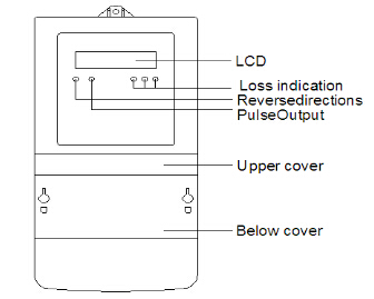
3.2 Display function
Power display 7 LCD (see Figure 2), including 6-bit integer, a decimal place. Units of kilowatt-hours, records accumulated meritorious total electricity consumption.
3.3 Communication indicator
When energy meter with external device communication, the communication indicator lights,indicating that it is in the communication status.
3.4 Output function
Passive isolated electric energy pulse output port, pulse output is a square wave pulse width of not less than 80ms±20%.
3.5 Programming function
The infrared setting the table number, Collecting power, set a password, electricity cleared.
3.6 Overload protection
Beyond the rated load energy meter Close.
3.7 Maximum demand function (optional) identifier A010.
4 The main technical indicators
4.1 Specifications and parameters in Table 1 below:
|
Product type |
Accuracy Grade |
Rated voltage |
Rated Current |
Pulse constant |
|
DTS 8888 Three- phase three- wire |
Class1.0 Or Class2.0 |
3×100V |
3×1.5(6)A |
6400imp/kWh |
|
3×3(6)A |
6400imp/kWh |
|||
|
3×230/400V |
3×1.5(6)A |
1600imp/kWh |
||
|
3×5(20)A |
800imp/kWh |
|||
|
3×5(100)A |
400imp/kWh |
|||
|
3×10(40)A |
400imp/kWh |
|||
|
3×15(60)A |
400imp/kWh |
|||
|
3×20(80)A |
200imp/kWh |
|||
|
3×30(100)A |
200imp/kWh |
|||
|
Continued on next page |
||||
4.2 Rated frequency:50Hz
4.3 Power consumption:Voltage circuit≤2W和10VA
Current circuit≤4VA
4.4 Operating ambient temperature:-20℃~+55℃,
Operating temperature limit:-45℃~+70℃。
Weight:About 1kg
4.5 Overall Size:291mm×144mm×71mm
4.6 The basic error in Table 2:
|
Load current |
Power factor COSφ |
Basic error |
|
|
Class 1.0 |
Class 2.0 |
||
|
0.05Ib≤I<0.1Ib |
1.0 |
±1.5 |
±2.5 |
|
0.1Ib≤I≤Imax |
1.0 |
±1.0 |
±2.0 |
|
0.1Ib≤I<0.2Ib |
0.5L 0.8C |
±1.5 |
±2.5 |
|
±1.5 |
—— |
||
|
0.2Ib≤I≤Imax |
0.5L 0.8C |
±1.0 |
±2.0 |
|
±1.0 |
—— |
||
4.7 Start
Energy meter at the rated voltage, rated frequency and power factor of 1.0, when the load current 0.4% Ib (1.0 level), 0.5% Ib (2.0 level). Energy meter should be capable of continuous measurement of electrical energy.
4.8 Creep
When applying 115% of the rated voltage, current loop disconnect, it does not produce more than one energy pulse.
5 Wiring
5.1 Wiring diagram
The energy meter connection shown in Figure 3
5.2 The functional terminal wiring is shown in Figure 9:
5.3 Function terminal to take the pulse signal reference is shown in Figure 10:
watt-hour meter function terminal to take the pulse signal with reference to FIG.
6 Meter reading, programming, calibration
6.1 Manual meter reading: View LCD display for meter reading.
6.2 Programmer meter reading: using TP800 programming meter reader, can be copied once not less than 500 tables of data (detailed see programming meter reading manual).
6.3 Meter RS485 interface, consistent communication protocol for remote automatic meter reading.
6.4 of meter calibration can be used two ways: First traditional photoelectric checksum method, photoelectric sampler flashing light-emitting diode pulse acquisition energy meter check; pulse check, use of auxiliary power meter terminal output opt coupler pulse signal calibration pulse signal with reference to FIG reference the ‘5 .3 function terminals Figure 10 ‘of the connection method.
7 Overall Description and install use
7.1 The energy meter structure is simple, easy to install, the shape shown in Figure 11 shows.
Note: The argument should prevail. Energy meter nameplate
7.2 The energy meter factory inspection and sealed letterpress printing, can be installed. Is no seal or storage of energy meter time is too long, you should ask the departments concerned to reinspection after installation, to ensure measurement accuracy.
7.3 meter should be installed in the room, select dry and ventilated place, the energy meter installed base plate should be placed in a strong refractory, difficult to shake the walls, it is recommended to install a height of about 1.8m, or installed on a dedicated distribution box. Specific installation dimensions shown in Figure 12.
7.4 Energy meter shall be wiring diagram for wiring and tighten the mounting screws, the introduction of the best copper connectors, to avoid the copper connector Terminal Block burned the watt-hour meter is due to poor contact.
7.5 In the thunderstorms more use of energy meter, lightning protection measures should be taken to avoid burned by lightning are so energy meter.
8 Transport and storage
8.1 Energy meter in the transport and unpacking should not be subject to severe shock, and in accordance with the provisions of the instrumentation packaging General technical conditions of transport and storage.
8.2 The stored energy meter should be packing conditions, save the environment temperature -25 ℃~ +75 ℃, relative humidity not more than 85%, and should not contain enough to cause corrosion of gas in the air.
8.3 Meter should be stored on the warehouse in the original packaging, placed in the bench, the height of the stack does not exceed the five-story, the unboxing single packaging energy meter stack height of not more than five inner packaging demolition the closure energy meter should not be saved.
9 Warranty and Service
Date energy meter from the factory, in compliance with the instructions required to use the right way, and found energy meter manufacturer seals still intact, does not meet the requirements stipulated by the technical conditions given eighteen months warranty.