.png)

Description
1.Overview
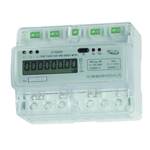
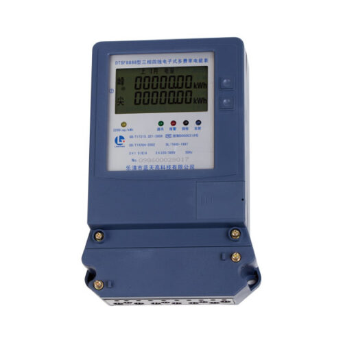
The electronic meter is our own development and production of multi-function electronic energy meter, the product uses advanced low-power LSI and SMT technology and advanced manufacturing technology, with high accuracy, stable performance, low power consumption and high reliability and other characteristics. A special selection of high performance energy metering chips and microprocessors, to ensure the accuracy and reliability of measurement used to measure the rated frequency is 60Hz (or 50Hz) of the three-phase power, and the use of LCD display power, set energy measure, no reactive energy metering and multi-rate and other functions into one unit and residents of the area for three-phase electrical energy measurement. Has the power display, optical communications and other features, users can power through the optical communication port for setting parameters or download the table records the data.
The meter meets the IEC62052-11, IEC62053-21/22/23 and other standards, communication line with IEC62056-21 standard.
2.Working principle
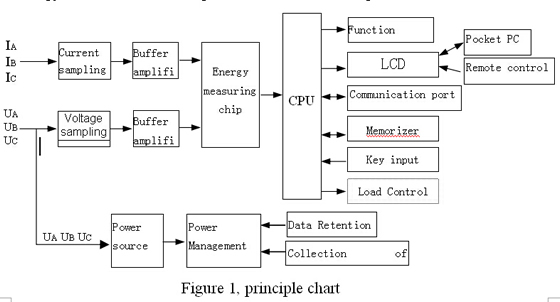
The meter is a measuring unit and data processing unit and other components, in addition to measuring active (reactive) power, but also with time-sharing, such as measuring the amount of two or more required functions, and can display, store and output data of the energy meter. Block diagram shown in See figure 1.
10)Climatic conditions
| Normal operating temperature | -20℃~+55℃ |
| Storage and transport temperature | -25℃~+75℃ |
| Storage and Humidity | ≤85% ( Non-corrosive gases in the air) |
11)Technical parameters
|
Multi-rate number |
4 |
| Multi-rate number of segments | 10×4 |
|
Measurement range |
0~999999.99 kWh,
0~999999.99 kvarh |
|
Display |
LCD |
|
Communication protocol |
IEC62056-21 |
12)Product specifications: see table below:
|
Type |
Rated voltage Un |
Rated current Ib(Imax) |
Accuracy class |
Pulse constant |
||
|
Active |
Reactive |
Active |
Reactive |
|||
|
3×120/208 V |
3×10(100) A |
1.0 |
2.0 |
400imp/kWh |
400imp/ kvarh |
|
|
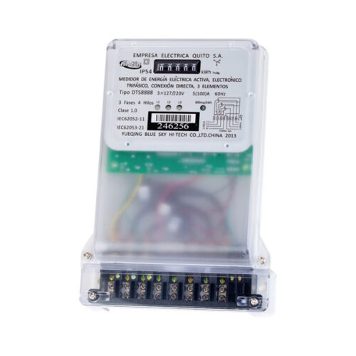
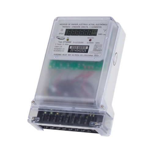
3×127/220 V |
3×10(100) A |
1.0 |
2.0 |
400imp/kWh |
400imp/ kvarh |
|
|
3×230/400V |
3×5(100)A |
1.0 |
2.0 |
800imp/kWh |
800imp/kWh |
|
3.Technical parameters
1)Executive standard:IEC62052-11,IEC62053-21/22/23, IEC62056-21
2)Accuracy class:Active 1.0 Reactive 2.0
3)Starting current:Active 0.004In (1.0)
Reactive 0.005In (2.0)
4)Rated frequency:60Hz
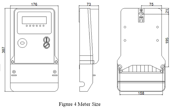
5)Dimensions:(307mm176mm73mm)
6)Weight:About 1.5kg
7)Day time error:< 0.5 s/d(23℃)
8)Parameters
| Normal operating voltage | 0.8Un~1.2Un |
| Operating voltage limit | 0.75Un~1.25Un |
| Voltage power consumption | ≤1.5W和4VA |
| Current power consumption | <1VA |
| Backup battery voltage | 3.6VDC |
9) Rate of the working parameters
| Clock accuracy (date error) | ≤0.5 s |
| Battery capacity | ≥1200 mAh |
| Data retention after power failure | ≥10 years (with new batteries) |
4. Function and Features
1) Energy Measurement
Positive active energy measurement of time-sharing, reverse total energy and demand.
Sharing positive reactive power measurement, reverse the total amount of reactive energy and demand measurement of active and reactive power.
2) Multi-rate function
4 kinds of rates can be set up(1、2、3、4).
Per day can be divided into 10 hours (minimum interval of 1min), a rate corresponding to each time period.
You can set up a time table set date.
3) Data record
User settings in the balance sheet date, the month of electricity consumption data automatically recorded and saved on the last month and last month’s electricity consumption data records. Measurement and save the needs of this month and last month the amount of its time of occurrence.
4) With the optical communications port, table number can be set to read power and other operations.
5) With high accuracy, stable performance, low power consumption and high reliability characteristics.
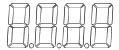
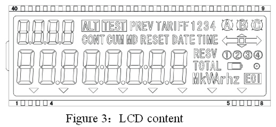
6) Large LCD display with 6 +2 read, the reading error, and liquid crystal display shown in Figure 3.
|
Symbol |
Meaning |
 |
Units of instruction:kWh—Active energy kvarh—Reactive Energy kVAh—Apparent energy kW —Active Demand kvar—Reactive Power Demand kVA—Apparent Demand
Ah—A/h |
 |
Battery Status: 3.6V battery voltage is low flashes |
 |
Significant signs hand wheel |
 |
Show last month, electricity consumption |
 |
Rates |
 |
Display hours, minutes, seconds |
 |
Display year, month, day |
 |
Demand countdown signs |
 |
Reverse |
 |
Total |
 |
Demand Reset |
 |
Show rates |
 |
Displays the current rate of state |
 |
Show ID numbers |
2) Meter Wiring
a. Functional terminal wiring diagram see Figure 5 (for reference, see the nameplate wiring diagram):
. Active or reactive power pulse output port diagram as shown in Figure 6:
Vceo≤80VDC(Option is less than 300VDC)
Note: The pulse width can be set to 20~250ms,The factory setting is: 80ms。
5. Appearance Description
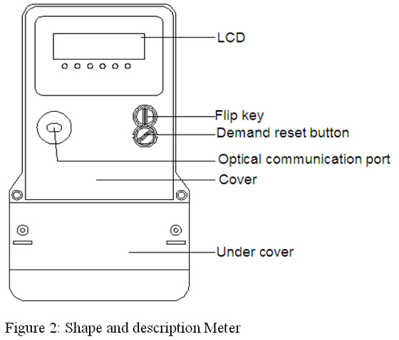
Note: The appearance of the chart for reference only, product to prevail in kind.
2) LCD display content as shown in Figure 3:
6. Installation and Wiring
1) Meter Installation
a. Meter in the factory have passed the test, and sealed letterpress printing, you can install and use. If there is no seal or too long storage time, energy meter, the relevant departments should be invited to re-inspection after the installation, to ensure measurement accuracy.
b. Meter should be installed in the room, select the dry and ventilated place, install the meter base plate should be fixed in the solid wall of fire, about the proposed installation height of 1.8m, or install a dedicated power distribution box.
c. Meter upper part of a hook screw holes, tied with the M6 screws, there are 2 meters lower mounting holes, use M6 screws in the terminal board general, energy meter Dimensions Figure 4.
d. Meter wiring diagram on the nameplate should be wiring, the best introduction of copper fittings to prevent the copper-side button box joint energy meter by leaving bad burn.
e. More places during a lightning meter, lightning protection measures should be taken to avoid leaving Meter lightning burned.
7.Transport and storage
1) Transportation
Meter in the transport and unpacking the impact should not be severe, and according to GB / T 15464-1995 “General instruments Packaging” the provisions of transportation and storage.
2) Storage
Meter storage conditions should be packaged and stored in an ambient temperature of -25 ℃ – +75 ℃, relative humidity of not more than 85%, and in the air should not contain enough to cause corrosion of the gas.
Meter should be placed in storage for safekeeping, under the conditions in the original packaging, placed in the bench, stacking height is not more than four, after unpacking the packaging alone energy meter stack height of not more than five, the packaging removed Energy meter seal should not be long-term preservation.
8. Warranty and Service
Meter from the date of sale within 6 months, follow the instructions in the user requirements, use of correct and complete in factory sealed condition, the failure can be found through meter agency contact the manufacturer repair or replacement.
Appendix A:Display list
By the measurement unit and data processing unit (CPU), LCD, optical communication port and other components, meter work, the analog signal (voltage, current) was measured after the chip into a digital signal, CPU to store data after the operation. Pocket PC or via PC with special software, the power of data and other information to read and copy parameter settings can also use the remote control, with the indicator on the meter display item for any inquiries.