.png)

Description
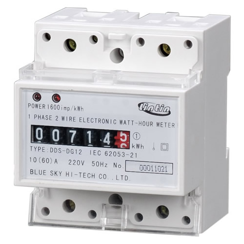
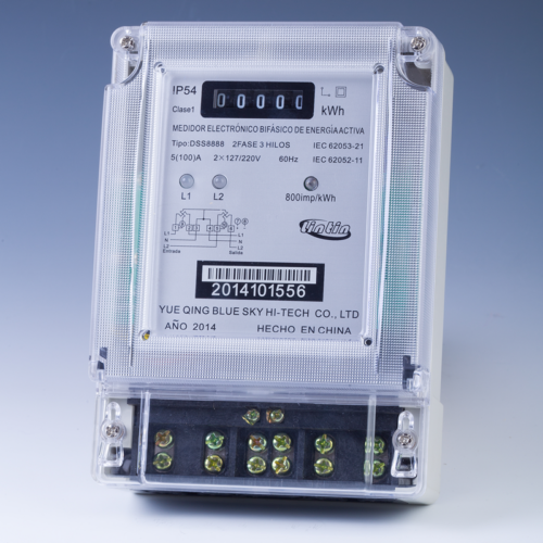
| 1 Product Brief Introduction The electronic power meter used to measure the rated frequency 50Hz (optional to do 60Hz), the reference voltage of 220V single-phase AC active energy. The product uses a special anti-theft function measurement circuit and SMT technology, to ensure measurement accuracy and reliability. The product complies with IEC62053-21, the IEC62052-11 standard. |
2The principle and structure 2.1 Working Principle block diagram shown in Figure 1.  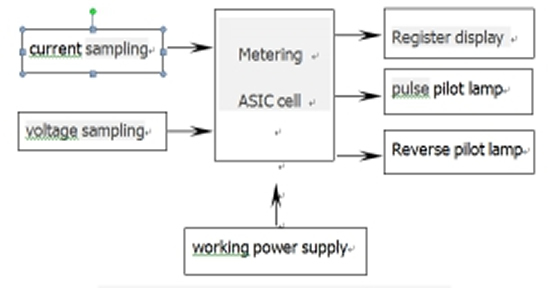 2. 2 The power meter phase line and neutral current is sampled. a) Phase line current the shunt sampling the voltage signal, the zero line current sampling the voltage signal. b) Comparator to compare the two branches of the current channel signal, and two larger signal value basis, compared to the difference of these two signals over 12.5% of the chip will output an alarm signal, the fault LED is lit. c) Measurement of electrical energy voltage signal sampling resistor divider, the chip’s internal error amplifier circuit to signal amplification, and then through the A / D converted to their proportional to the digital signal into another input of the digital multiplier the current channel signal multiplication to complete the measurement of the instantaneous power of the measurement of electrical energy. placed on the press box on the” up “. d) Multiplier output instantaneous power through a digital low-pass filter with integral handle into the “digital / frequency converter, to transform into and electrical energy has been measured at average power is proportional to the frequency of the pulse signal (divided into high-frequency pulse signal and the low-frequency pulse signal)The high-frequency pulse output to parity with the micro-processing interface, to achieve energy metering. |
|||||||||||||||||||||||||||||||||||||||||
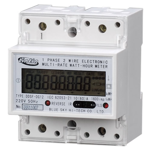
| 3 The main function 1) high reliability, simple structure, high measurement accuracy and other characteristics; 2) low power consumption; 3) low starting power; 4) anti-tampering design, stealing as to minimize the reverse electricity can still be properly recorded power; 5) measurement design, with anti-theft function; 6) has a power supply, pulse, reverse indicator light; 7) with , table number set, the power read operation; |
||||||||||||||||||||||||||||||||||||||||||
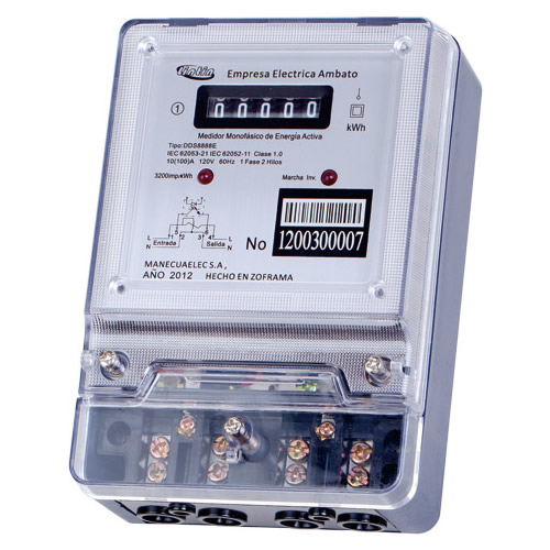
| 5 Shape structure The power meter is a simple structure, beautiful appearance, the main structure with fire-retardant features, the shape shown in Figure 3.  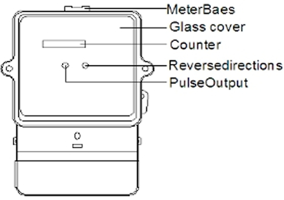 |
||||||||||||||||||||||||||||||||||||||||||
| 4 Technical indicators 4.1 Specifications and parameters shown in table 1 (according to customer requirements):
4.2 The basic parameters of
4.4 Start |
6 installation and wiring 6.1 watt-hour meter at the factory have passed the test and affix the seal, you can install and use. The meter should be installed within the room or meter box (cabinet) to use, install the base plate of the table should be fixed on a sturdy fire-resistant walls, it is recommended mounting height of 1.8 meters (mounting dimensions see Figure 4 below). 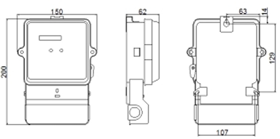  Note; the installation process, if the power meter by the severe impact or high-altitude drop the shell has obvious signs of damage, not on the table installation, power, and contact your supplier as soon as possible; 6.2 Wiring Energy meter cover screws with a screwdriver, open the cover and then the screwdriver from the 1, 2, . 3, 4 screw terminals on the , and then follow the wiring diagram into line with the outlet exposed end into the corresponding terminal holes, then screw tighten the upper and lower lid can be used (direct access to the wiring diagram shown in Figure 4). 5, 6 terminal, the pulse signal output for error detection or automatic meter reading system interface. 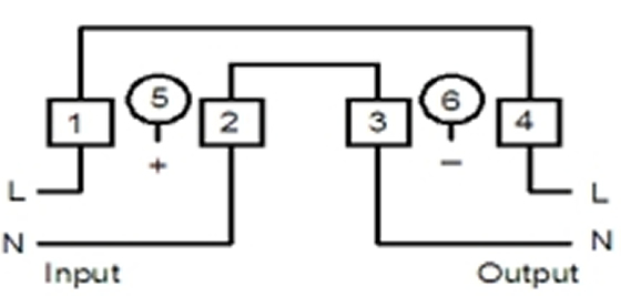  Figure 4 direct access to the wiring diagram |
|||||||||||||||||||||||||||||||||||||||||
| 7 Transport and storage 7.1 Transport and storage environment Temperature range: -25℃~+70℃ Annual average relative humidity: ≤ 75% There should be no corrosive gas in the air 7.2 Transport Transport and disassembly of the power meter should not be subject to severe impact, transport and storage in accordance with the provisions of the GB/T15464-1995 instrumentation packaging generic technical conditions “, the requirements 7.3 storage The meter should be stored in the warehouse and placed on shelves, stacked height of not more than 5 boxes, unpacking after the single energy meter stack height of not more than 10. |
8 warranty with the services Power meter since sold eighteen months from the date of compliance with the user manual requirements, and complete power meter does not meet the requirements of national standards in the factory seal, the manufacturer give free repair or replace |
|||||||||||||||||||||||||||||||||||||||||