.png)

Description
1.Product introduction
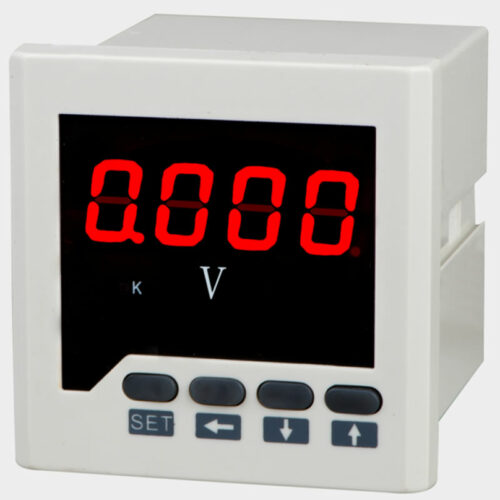
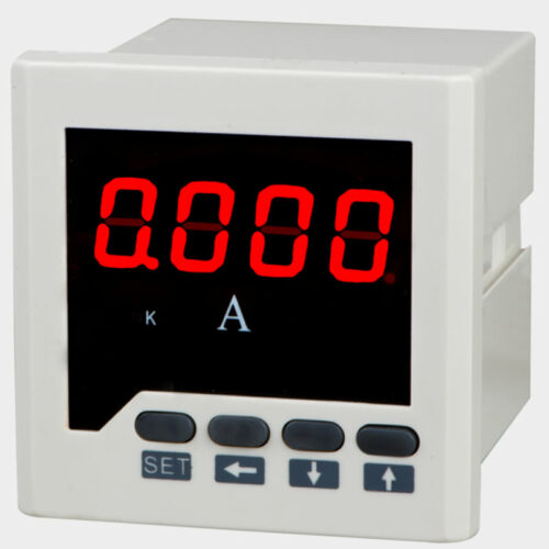
Intelligent three-phase active power and reactive power meter is one kind of programming measurement, display, alarm, digital communication and analog quantity output sent to other functions of the intelligent instrument, widely used in substation automation, distribution automation, intelligent building, automatic production lines, test station. True RMS measurement, high precision, good stability. Transformer ratio can be set through the instrument key, it is convenient and flexible to use。
Four bright red LED display; option the second road relay alarm output, implementation, the lower limit alarm function; optional RS-485 digital communication interface, use the standard MODBUS-RTU communication protocol, with a variety of PLC, HMI, configuration software to achieve network; optional analog quantity DC4 ~ 20mA analog output.
2.technical parameter
|
parameter |
performance |
||
|
Signal input |
Voltage |
range |
100V 220V 450V 57.7V, etc. |
|
overload |
Continued:1.2 times, instantaneous:2 times /1S |
||
|
Consumption |
<1VA |
||
|
impedance |
>380KΩ |
||
|
electric current |
range |
AC 5A/1A |
|
|
overload |
continued:1.2times,instantaneous:10times/5S |
||
|
Consumption |
<1VA |
||
|
impedance |
<20mΩ |
||
|
frequency |
45-65HZ |
||
|
Auxiliary power supply |
Linear power supply: AC220V±5%;power waste<3VA Switching Mode Power Supply: AC/DC85-265V、DC10-36V;power waste<3VA |
||
|
Relay output |
Two way output, contact capacity:1A/220VAC;1A/24VDC |
||
|
Analog output |
DC4~20mA |
||
|
RS485 communication |
RS485 communication interface, physical layer isolation, in line with the international standard MODBUS-RTU protocol Baud rate 4800,9600, N81 data format |
||
|
Precision grade |
0.5 |
||
|
Display mode |
Digital display: 4 high brightness LED digital tube |
||
|
Environment |
working temperature:-10-55℃;Storage temperature:-20-75℃ |
||
|
security |
Insulation: signal, power supply, output terminal to shell resistor > 5M
Voltage: signal input, power supply, output between > AC2KV |
||
3. Appearance size and size of opening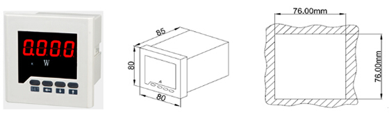 3.1Appearance size and size of opening
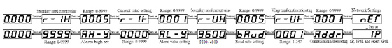
4. Panel button operation |
||||||||||||||||||||
| 6.functional module 6.1 Relay alarm output Relay contact capacity:1A/250VAC,1A/24VDC。  Relay work in, the lower limit alarm, two alarm parameters setting: limit alarm value (the value of the secondary side) and the lower limit alarm value (the value of the secondary side), the upper limit alarm: when the measured value exceeds the limit alarm value, the high limit alarm relay, when the upper limit alarm after the action of the electric, only when the measured value is less than the upper limit alarm value, the upper limit alarm reset relay. Lower limit alarm note: when the measured value is lower than the lower limit alarm value, lower limit alarm relay, when the lower limit alarm relay action, only when the measured value is greater than the lower limit alarm value and the lower limit alarm reset relay。 6.2 Send an analog quantity output Send an analog quantity output optional: DC4 ~ 20mA. An analog quantity output and input signal isolation, a linear corresponding relation are widely used for PLC, DCs were collected. Precision of 0.5 grade; output current, load resistance < 500 ohms, output voltage, load resistance > 100k ohm。 6.3 RS485 communication 6.3.1 communication protocol (1) RS485 communication interface, asynchronous half duplex mode。 (2) 4800,9600bps baud rate can be set, the factory default value is 9600 BPS。 (3)Data format: N81 no parity bit, 8 data bits, 1 stop bits。 RS485 interface; connection type: asynchronous, half duplex; international standard Modbus RTU protocol instrument address: 1~247, baud rate 48009600, data format: N81 no parity bit, 8 data bits, 1 stop bit; the machine currently supports 03h read command。 Message format description: command03H:Read command Host request: Address + Command + data address + data length + CRC check code 1byte + 1byte + 2byte + 2byte + 2byte Address: in order to check the instrument address code, you can set up in the 1~247, take up 1 bytes。 Command: 03H read command, the length of 1 bytes。 Data address: want to read the data starting address, occupy 2 bytes。 Data length: the length of the data word to be read。 CRC16 check code: high 8 in the front, low 8 in the post, occupy 2 bytes。 Slave response:Address + Command + data + data + CRC check code 1byte + 1byte + 1byte + nbyte + 2byte Address: in response to the meter address code, the length of 1 bytes。 Command: 03H, length is 1 bytes.。 Data length: the length of the data bytes to be sent。 Data information: read the data, specific see meter parameter address table。 CRC16 check code: high 8 in the front, low 8 in the post, occupy 2 bytes。 6.3.2 Example of communication message: Read data register (function code 03H): read the power value, the current 100.1W, the instrument address is 1。 Host read data frame:
Instrument response data frame:
|
6.3.3 ModbusCommunication register address table
|
address |
Project description |
data type |
attribute |
explain |
|
9、10 |
Power value |
float |
R |
Meet IEE754 floating point standard |
|
8 |
Open out value |
Short |
R |
Range:1~9999 |
EEE754Data format description
IEEE754Is the use of 4 bytes of binary floating-point numbers to represent a data quantity, the data format and significance are as follows:
| Byte address | BYTE1 | BYTE2 | BYTE3 | BYTE4 |
| Floating point content | SEEEEEEE | EMMMMMMM | MMMMMMMM | MMMMMMMM |
Symbol bit:S=0 is positive, S=1 is negative.。
Index part:Order code=E-127。
Mantissa part:Mantissa=M up to the highest level of 1
Data result:
7.Connection mode and terminal diagram
7.1 Connection mode
Electric current transformer Direct current Voltage input


7.2 Terminal diagram
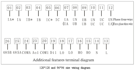
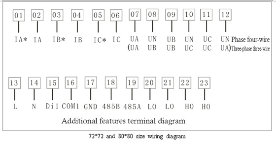
Description: 1, If the terminal diagram is different with the actual terminal diagram which at the back of the product, please according to the terminal diagram which is at the back of the product 2, Ho is upper limit alarm relay output, Lo is for lower limit alarm relay output and AO1 analog output.